Rules for the footprints management
Let's now describe in detail the general rules of footprints creation.
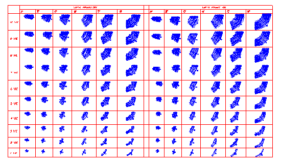
Rule 1: "Each table must show one and only one type of component (or its subfamily)"
Each table must contain a single type of component. A component can be:
- • An object type (curve, rectilinear structure)
- • A machine part
- • An accessory that can be placed on multiple machines (shared)
It's important not to include components of different types within the same table.
Rule 2: "Each table must contain the different models of the component (dependent from variables)"
Each table must contain all the models for each component. Model means a component in all its configurations. You need to establish the parameters that define the different component configurations. For example, in a conveyor belt curve, you can be considered "number of paths", "angle" and "radius". In order to maintain a certain order of the document for a possible subsequent revision, it is appropriate to arrange all items in a grid whose rows and columns represent distinctive parameters for the rapid detection of the component. Consequently, for each crossing or box, only one footprint will appear.
Rule 3: "The TOP part name must match the name of the file"
It's a good idea that the TOP part name matches the name of the drawing.
Rule 4: "Each model configuration must be defined by a part"
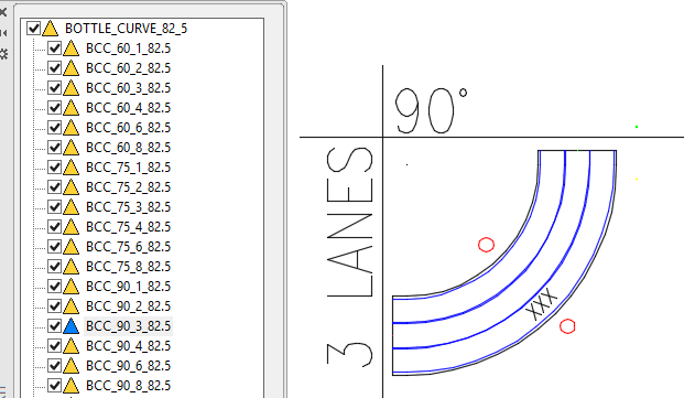
Each configuration of each model must be defined by a first level part of the drawing (daughter of the TOP part). In the case in question, for example, we will have one part for each combination of "number of paths", "angle" and "radius".
Rule 5: "Each configuration part can contain subparts"
Every single configuration part may contain an internal structure of parts. This structure may be defined in accordance with the design and/or counting requirements. If the footprint is a complex component, you must create subparts identifying accessories that rest on the main piece. For example, a tiling can be constituted by the main body, but also by feet, engines, wheels... For each piece of this type, you must therefore create a subpart always with unique name.
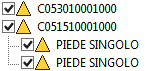
NIn the case in question, for example, two parts were introduced for bearing.
 It's very important that parts common to most components always have the same name. For example, if you must use the same type of foot in other footprints, it is good practice to remember to use the same part name.
Rule 6: "The configuration part name must contain characters compatible with the Windows filesystem"
The names of the parts should be created using a significant coding or descriptive names. It's important to try to use names that are not too long and avoid using characters not allowed in Windows filenames. A safe rule is to avoid using the following characters:
. " / \ [ ] : ; | = , * ?
It may be a good idea to use a simple mnemonic code. It's important to give each footprint a unique part name in order to be able to effectively find the library. For example, an exhaustive nomenclature can be formed from the component family, followed by the number of paths of the two inputs, the number of paths of the two outputs as well as any final characters that represent the version. In this way, you get a mnemonic code certainly more useful than a random code. A curve of the CCC family with 4 inputs can be translated by the previous example in "CCC04000400".
Rule 7: "The parts whose name begins with dot are discarded by the export process and are considered comment parts. The TOP part is discarded by the export process"
All first level parts, whose name starts with dot, are considered "comments parts". These parts are ignored by the footprints generation program.
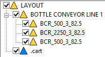
In the example, the ".cart" (title block) part will not be exported as a footprint. The TOP part (the base part of the drawing) is automatically discarded from the footprints generation process.
Rule 8: "It's advisable to enter all the information needed to maintenance in the table. Use the comment parts to contain this information"
It's a good idea to comment the tables in a comprehensive way, by entering all the information necessary for the proper maintenance of the footprints. For example, it may be useful to include a description of the parameters that define the component model. To prevent the comment graphics is exported as a footprint, use the "comment parts". Some comments can be placed in the TOP part.
Rule 9: "Every footprint part shall be formed properly by having positioned correctly the mates necessary for automation"
Because a footprint can operate properly, it must contain a series of particular objects called mates, each presiding over one specific function. The mates description is provided later in this document. The important thing to remember is that these mates shall be inserted with care, aggregating them to the part and placing them to the right coordinates and with the proper angle.
Rule 10: "If automation is also required for subparts, each subpart must be correctly formed"
There are special components that must contain other components (reinserted in the positioning phase of the layout). Each of these sub-components must be well-formed (see Rule 13). Consider, for example, a "tiling" part that contains an N "motor" part. The motor part must be a tiling subpart and must contain all mates necessary to define its behavior.
Rule 11: "The footprint signature shall be entered as MTEXT inside the part and must contain a text with the agreed code (i.e." XXX ")"
In some cases, it is necessary to have the texts defined in the phase of insertion of the component in the layout. These texts are usually intended to contain the information available only after the component has been inserted in the layout. To make sure that the program can recognize the correct fields and set them with the necessary data, you must enter such texts aggregating them to the part and assigning them a default value to be agreed (i.e. "XXX"). During the insertion of the part, the program will automatically look for texts within the part with defined text and will set them to the correct value.